Operating and Maintenance Instructions For GASO Triplex Plunger Pumps
SERIES 3211, 3364, 3466, 3500, 3800, AND 3900(EXCEPT FIG. 3583-A)
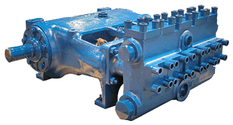
GASO HORIZONTAL TRIPLEX PLUNGER PUMP
Follow These Instructions Carefully And You Will Help Insure Trouble Free Operation For The Life Of Your Pump.
GENERAL PRECAUTIONS PRIOR TO STARTING PUMP
- Level pump to insure proper lubrication during operation.
- Verify that pump crankcase has been filled with the proper amount of lubricant.
- Verify that packing has been properly installed in the pump and is properly tightened.
- Tighten all stud nuts and cap screws to the recommended torque values.
- Squirt a light oil or other lubricant on the plungers and rotate pump by hand to verify free rotation.
- When force feed lubrication is used, verify that the lubricator is filled and is operating properly.
- Flush all suction lines leading to the pump. This will help protect valves and seats from damage.
- For plunger and packing protection, always prime pump. Verify that fluid fills the chamber in front of the plunger. This is a positive displacement pump and is not intended to operate dry. This pump is designed to operate in a cavitation-free system.
- Verify that all valves in discharge piping are open.
WARNING:
AN OPERATIONAL SAFETY RELIEF VALVE MUST BE INSTALLED IN THE DISCHARGE LINE BETWEEN PUMP AND ANY OTHER PIPE FITTINGS. THIS RELIEF VALVE MUST BE SET AT THE RECOMMENDED RELIEF PRESSURE DESIGNATED ON THE PUMP APPLICATION TAG. CATASTROPHIC DESTRUCTION OF PUMP, PIPING, OR PERSONAL INJURY MAY RESULT IF DISCHARGE LINES ARE CLOSED WHEN THE PUMP IS STARTED, OR AFTER THE PUMP IS RUNNING.
topII. GASO TRIPLEX PLUNGER POWER PUMPS POWER END
POWER END PLUNGER CRADLE COVER - -
The plunger cradle is the area behind the liquid end stuffing box packing in the power frame where the plungers are located. Standard plunger cradle covers are sheet metal and are intended to reduce the amount of foreign matter entering - the cradle area. Occasionally, a gasketed, vapor-tight cover is furnished to allow vapors from the liquid being pumped to be piped away from the pump or away from a hazard near the pump.
WARNING! THIS VAPOR-TIGHT COVER IS NOT INTENDED NOR DESIGNED TO HOLD PRESSURE! VAPORS MUST BE VENTED TO ATMOSPHERIC PRESSURE! IF SUBJECTED TO PRESSURE, EXTREME DANGER WILL EXIST. THE COVER MAY BLOW OFF THEREBY CREATING AN EXTREME HAZARD!
topLUBRICATION --
All parts in the power end are lubricated by splash from lubricant in the crankcase.
WARNING! Crankcase is drained after testing pump at factory. Remove the narrow crosshead guide hand hole cover on top of the frame and add sufficient lubricant before starting the pump.
topCRANKCASE OIL --
Quantity of lubricant necessary to fill crankcase to the proper level is shown in the table below. For pump speeds below 150 RPM, oil level must be at the center-line of the crankshaft.
For pumps operating in average climates, use SAE 9OEP AGMA SEP, or AGMA 6EP gear lubricants. Be sure, however, to use an EP lubricant that will not have a corrosive action on bronze and that it contains rust, oxidation, and foam inhibitors. Multipurpose/multi-viscosity gear lubricants are UNSATISFACTORY for use in GASO pumps.
|
PUMP SERIES |
3211 |
3364 |
3500 |
3800 |
3900 |
|---|---|---|---|---|---|
|
U.S GALLONS |
5 |
2 |
8 |
9 |
8 |
As soon as above lubricant has been added, replace crankcase cover and install breather(s)on top to provide for ventilation.
Running temperature of crankcase oil should not exceed 180 degrees Fahrenheit. If higher temperatures occur and mechanical fits are found to be correct, -the use-cf a separate oil cooler is recommended.
For low ambient temperatures,. select an oil with a pour point lower than the lowest anticipated ambient temperature. Consult GASO factory for recommendations when unusual operating conditions exist.
topDAILY INSPECTION OF OIL IN CRANKCASE -
Check oil level and appearance daily. Change oil and clean breather every six months or 2,000 hours running time; more often under severe operating conditions. The crankcase should he thoroughly cleaned at each oil change. Contamination of the oil by saltwater will be indicated in only a few hours by the oil turning -white, milky, or foamy. Contamination of the oil by moisture condensation will be indicated by the oil slowly turning dark or a rusty brown. Whenever any type of contamination or dilution is detected, drain the crankcase, remove the crankcase cover, and crosshead guide hand hole cover, thoroughly flush out the oil and refill with clean oil as necessary to bring to full mark on the dipstick. Do not overfill. At the same time, check and clean the breather. Oil lost by leakage should be replaced before the level becomes too low. If loss is excessive, check the packing in the crankcase stuffing boxes, the oil retained on the pinion shaft, and clean the crankcase breather.
topCRANKCASE STUFFING BOX FOR PLUNGER ROD --
Packing for the plunger rod is double u-cup packing or non- adjustable lip type packing. The double u-cup packing is a single ring and requires no bottom ring or spacers. The packing gland should be metal to metal with the power frame and should not tighten on the double u-cup ring. See instruction sheet with packing.
The non-adjustable lip type packing should be tightened firmly. Further tightening will not affect the packing sealing efficiency. New packing may leak slightly, but should gradually seal itself.
The packing in this stuffing box serves two purposes. It prevents lubricating oil from escaping the crankcase and prevents outside fluids from entering the crankcase. It is very important that these stuffing boxes be checked while pump is running and that new packing be installed at once if proper gland adjustment does not stop excessive oil leakage or leakage of contaminant into crankcase. See instruction sheet furnished with packing units for detailed information for installation and replacement.
topCONNECTING ROD BEARINGS, CRANK END --
Adjust or replace these bearings at first sign of wear. The bearings in the crank end are babbitt lined steel shells, adjustable for wear by removing shims and easily replaced when completely worn. These bearings should be watched closely and adjusted at first signs of looseness.. You will note on series 3400, 3800, 3500, and 3900 pumps, that the shims do not completely fill the outer gap between rod and cap casting, although the connecting rod bolts are tight. This is because the faces of the shell bearings project slightly beyond the faces of the rod and cap castings, and the shims are gripped only between the faces of the bearing halves. Do not try to close this outer gap by tightening the connecting rod bolt as it will put an excessive strain on the bolts.
To check for wear, place a wrench on the top connecting rod bolt and shake the rod parallel to the crankshaft. (The pressure must be relieved from the liquid end of the pump, so that the pump is mechanism is free to move.) If the rod bearing moves without resistance, the bearing may be too loose and need adjusting. If the bearing does need adjusting, remove shims until you cannot shake the rod, then add .005î shims one at a time until there is little side movement. Be sure to torque rod bolt nuts to proper value for each adjustment. Oil clearance should be checked with Plastigage (available in most parts stores). Wipe crankshaft journal clean of any oil, place a strip of Plastigage on the crankshaft journal and tighten rod cap to the proper torque value. Once tightened, remove rod cap and measure oil clearance with scale on Plastigage package. See oil clearance chart. (NOTE: If you are making this adjustment after having had the crossheads out, be sure that the oil holes in the rod are pointing up. The up side is indicated by matching numbers stamped on the cap and rod at the split between them. These numbers should be the same on each rod and should be on the top side of the crankshaft.) Rotate the shaft by hand and if there is any hard drag or tight spots in the bearing, add another 0.005î shim. After this bearing is properly adjusted, loosen bolts a few turns and repeat the above operation on the other bearings. After all bearings have been adjusted.
Torque all connecting rod bolt nuts back to proper value. Again rotate the pump by hand to check for excessive drag and tight spots. If none, the pump should be ready for operation.
If the pump cannot be rotated by hand due to the drive being enclosed, care must-be taken: not to over-tighten the bearings, since they cannot be checked by rotating the pump. When bearings are adjusted by this method, watch carefully for overheating when the pump is put into operation.
It is usually better to have a bearing a little too loose than too tight. A slightly loose bearing will cause very little trouble because of the slow operating speeds of the pump, but a tight bearing will overheat and the babbitt may melt or pull. Normal precautions must be taken to insure cleanliness of parts upon their assembly.
topCLEARANCE ON CONNECTING ROD BEARINGS, CRANK END
|
PUMP SERIES |
1800 |
2200 |
1500 |
2000 |
1600 |
1700 |
1900 |
2600 |
|---|---|---|---|---|---|---|---|---|
|
U.S GALLONS |
2.5 |
5 |
6 |
10 |
8 |
10 |
15 |
18 |
CONNECTING ROD BEARINGS, CRANK END -
Inspect connecting rod bearings and adjust as necessary every six months or when crankcase lubricant is changed. The bearings in the crank end are babbitt lined steel shells, adjustable for wear by removing shims and easily replaced when completely worn. These bearings should be watched closely and adjusted to compensate for wear. You will note that shims do not completely fill the outer gap between rod and cap casting although the connecting rod bolts are tight. This is because the faces of the shell bearings project slightly beyond the faces of the rod and cap castings and the shims are gripped only between the faces of the bearing halves. Do not try to close this outer gap by tightening the connecting rod bolt as it will put an excessive strain on them.
To check for wear, place a wrench on the top connecting rod bolt and shake the rod parallel to the crankshaft. (The pressure must be relieved from the liquid end of the pump so that the pump's mechanism is free to move.) If the rod bearing moves without resistance, the bearing may be too loose and need adjusting. If the bearing does need adjusting, remove shims until you cannot shake the rod, then add .005'' shims one at a time until there is a little side movement. Be sure to torque rod bolt nuts to proper value for each adjustment. (NOTE: If you are making this adjustment after having had the crossheads out, be sure that the oil holes in the rod are pointing up. The ''up'' side is indicated by matching numbers stamped on the cap and rod at the split between them. These numbers should be the same on each rod and should be on the top side of the crankshaft.) Turn the shaft by hand and if there is any hard drag or tight spots in the bearing, add another .005'' shim. After this bearing is properly adjusted, loosen bolts a few turns and repeat the above operation on the other bearings. After all bearings have been adjusted, torque all connecting rod bolt nuts back to proper amount. Again turn the pump by hand to check for excessive drag and tight spots. If none, the pump should then be ready for operation.
If the pump cannot be rotated by hand due to the drive being enclosed, the bearings may be completely adjusted by shaking the bearing on the shaft as stated above. Care must be taken not to over-tighten the bearings since they cannot be checked by rotating the pump by hand. When bearings are adjusted by this method, they must be watched carefully for overheating when the pump is put into operation.
Alternatively, plastic gauge strips, found in most parts stores may be used to adjust these bearings. It is usually better to have a bearing a little too loose than too tight. A slightly loose bearing will cause very little trouble because of the slow operating speeds of the pump, but a tight bearing will overheat and the babbitt may melt or pull. with experience, an operator can tell by feel when the bearings are properly adjusted. Normal precautions must be taken to insure cleanliness of parts upon their assembly. All wrenches used in adjusting these bearings are standard wrenches.
|
PUMP FIGURE NUMBER |
DIA. OF CRANK PIN |
CLEARANCE |
|---|---|---|
|
3211 |
2.50'' |
.002'' |
|
3364 |
3.25'' |
.002'' |
|
3400-3900 |
3.75'' |
.002''-.003'' |
|
3500-3900 |
4.50'' |
.002''-.003'' |
RECOMMENDED TORQUE WRENCH SETTINGS FOR CONNECTING ROD BOLT NUTS
|
TORQUE |
500 In. -Lbs. |
1000 In. -Lbs. |
4000 In. -Lbs. |
|---|---|---|---|
|
PUMP FIGURE |
3211 |
3364 |
3400 |
|
. |
|
2900 |
3500 |
|
. |
. |
. |
3800 |
|
. |
. |
. |
3900 |
|
. |
. |
. |
. |
|
. |
. |
. |
. |
|
BOLT SIZE |
1/2'' |
5/8'' |
1'' |
CONNECTING ROD BEARINGS, CROSSHEAD END -
Bearings in the crosshead end are bronze bushings. To replace these bushings remove connecting rod and crosshead assembly from pump, press out the crosshead pin, and then remove and replace the bushing. After the new bushing has been pressed into the connecting rod, it should be reamed for a loose fit on the crosshead pin as follows; .0015î for Fig. 3211; .002î for pumps Series 3300, 3400, 3500, 3800, and 3900.
Before replacing crosshead pin, always inspect pin and crosshead for burrs. Then press-in pin, using an anti seize compound as lubricant. -
topCRANKSHAFT BEARINGS -
For pumps Series 3200, 3300, 3400, 3500, 3800, and 3900, the crankshaft bearings arc single tapered roller bearings automatically lubricated from oil in the crankcase. These should be flushed clean and carefully inspected at least once every six months, or whenever crankcase lubricant is changed. Also check for wear and possible need of adjustment at these times. End play of crankshaft should not exceed .003î (measured when pump is cold to allow for expansion due to heat under operating conditions)
Bearings may be adjusted from one side only. To adjust bearing, disconnect connecting rods, remove several shims (more than necessary) from under the bearing housing, tighten crankshaft bearing housing cap screws until bearings bind slightly when shaft is rotated by hand. Then measure the shim gap with a feeler gauge and add its equivalent plus from .001" to .003î of shims (for normal clearance) and tighten crankshaft bearing housing cap screws. When necessary to install new bearing cones on crankshaft, heat bearing in oil at 280 degrees Fahrenheit for easy installation. Be sure bearings are firmly against the shoulder on the crankshaft.
Please note: Improper application of heat to these bearings during their installation in GASO pumps will automatically revoke the warranty on the bearings. It is suggested that the procedures outlined above be closely followed when changing bearings.
topII. GASO TRIPLEX PLUNGER POWER PUMPS FLUID END
GASO HORIZONTAL TRIPLEX PLUNGER PUMPS LIQUID END PLUNGER STUFFING BOXES AND PACKING --
These are among the first liquid end parts that should receive attention when starting up a new pump. The liquid end stuffing boxes on new pumps have been packed at the factory, and adjusted, but the packing may need further adjustment as. the pump .is put into service. DO NOT ATTEMPT TO ADJUST PACKING WHILE PUMP IS RUNNING. Standard packing for the plunger rod consists of a set of a set of special non-adjustable lip type packing rings. New packing may be expected to leak slightly for a day or so, but will gradually seal itself. Lips on the packing rings will eventually wear, and allow excessive leakage which cannot be prevented by further tightening of the gland. It will then be necessary to replace the packing rings.
Bronze lantern rings for force feed lubrication are furnished as standard equipment.
Standard packing glands for pumps Series 3200, 3300, 3400, and 3500 are held in place by studs and nuts, and enter into stuffing boxes which are integral to the liquid body. They are intended for use only with standard non—adjustable type packing in systems where the pump experiences no cavitation. Gland stud nuts should be tightened sufficiently to prevent movement of the packing gland when the pump is operating under pressure. If packing gland movement is not prevented, the gland stud may experience fatigue failure.. If stud failure occurs, ALL STUDS ON THAT GLAND MUST BE REPLACED! If soft, adjustable packing is used, or if packing gland movement cannot be prevented, or if the pump experiences occasional cavitation, screw type packing glands must be installed to minimize the possibility of pump failure.
Standard packing glands for pump Series 3800 and 3900 are screw type, attached to removable stuffing boxes which are different sizes for different size plungers. Packing glands must be kept securely tight at all times to prevent movement of the packing and to utilize the non-adjustable feature of the packing efficiently. Packing and stuffing box replacement instructions are available upon request.
topPLUNGERS - -
Plungers of various materials are-available: namely; file hard steel, steel with hard colmonoy surface and ceramic. Ceramic plungers will give the longest wear life, but must be used and handled very carefully; They will fracture easily-from transverse blows or stresses. Therefore, extreme care should be exercised when installing them to be sure they are perfectly centered in the stuffing boxes after the plungers or nuts are tightened. When using special adjustable packing, avoid too tight packing, as the friction would cause excessive heat on the plunger. The temperature differential between the hot plunger and cold fluid being pumped could cause a heat fracture in the ceramic plunger.
Standard plungers for pumps Series 3200, 3300, 3400, and 3800 are one-piece and are connected directly to the crosshead. A neoprene baffle disc rides on the shank of the plunger to help prevent fluid from moving down to the crankcase stuffing box. To change plungers, remove the cylinder head, disconnect the plunger, and withdraw plunger through the cylinder head opening. Install the new plunger in reverse procedure. The plungers are threaded directly into the crosshead. The 3200 and 3300 plungers are held in place by jamming the shoulder of the plunger against the face of the crosshead. The 3400 and 3800 plungers are held in place by a lock. These faces must be absolutely clean, free of burrs, and dry to effect a tight joint.
Plungers for pumps Series 3500 and 3900 are connected to the crosshead by an extension or plunger adapter rod which is held in place by jamming the shoulder of the adapter rod against the face of the crosshead. Plungers are threaded directly into the adapter rod and are held firmly in place by jamming. the shoulder of the plunger against the end face of the adapter. These faces must be absolutely clean, free of burrs and completely dry to effect a tight joint. Join plunger to adapter by using wrench surfaces provided on each piece near the joint. To change plungers remove the cylinder head, unscrew plunger, and then withdraw the plunger through the cylinder head opening. Install the new plunger in reverse procedure. Plunger adapter rods can be replaced without removing cylinder heads.
Be sure that all joints are definitely tight before putting the pump into operation.
Force feed lubrication is recommended for all job applications of Series 3500, 3800, and 3900 pumps. Complete plunger lubrication recommendations available upon request.
The main sprocket is of alloy steel, with internal flange for bolting to center disc of crankshaft. To remove crankshaft and main sprocket, pull master link from chain, remove cap screws holding oil seal rings to inner end of main bearing housing, remove bearing housing clamps and pull main bearing housings outward until free of bearings. Then lift crankshaft and gear assembly out. Support crankshaft and sprocket assembly with a block or hoist before pulling the bearing housing outward.
topVALVES - -
Pump figures 3211 and 3364 have wing guided type valves and seats as standard equipment. Hardened and ground steel valves and seats are used for crude oil service. Stainless steel, aluminum bronze, or monel valves and seats are used for saltwater service and other corrosive liquids. These must be kept in good condition for efficient operation of the pump. All but steel valves can be re-ground against their seats with grinding compound while in the pump. The steel valves and seats will have to be removed when worn and re-ground in a machine shop or replaced.
3400, 3500, 3800, and 3900 series pumps are equipped with stem guided monel, bronze or stainless steel disc type valve assemblies with delrin, stainless steel, or monel discs. Suction and discharge valve assemblies are identical within their respective liquid ends with direct interchangeability between Fig. 3365 and Fig. 3467, and between Fig. 3466, Fig. 3581, Fig. 3868, and Fig. 3969 pumps. Worn valve discs may be easily replaced by removing guard from top of stem. To remove the seats, pull discharge seat first and then lower pulling tool through opening in discharge seat deck to pull suction seat. When replacing seats, clean valve seat and mating taper in pump with a cleaner that does not leave an oil film or residue. Wipe with a clean, dry rag. CAUTION: SEAT AND TAPER IN PUMP MUST BE ABSOLUTELY CLEAN AND DRY BEFORE DRIVING SEAT INTO PUMP TAPER.
Cylinder heads and valve covers for Figs. 3211 and 3364 pumps are threaded and are provided with an internal hexagonal shaped recess for insertion of a special wrench furnished with the pump. These should be tightened very securely with the aid of a light hammer and the special wrench.
Cylinder heads and valve covers for 3211 and 3364 with steel block type liquid bodies are bolted to the liquid bodies with cap screws.
Cylinder heads and valve covers for the remaining pumps, Fig. 3365 and Series 3400, 3800, 3500, and 3900 are bolted to the liquid bodies with studs. The stud nuts and cap screws must be tightened evenly and torqued to the setting given in the chart below.
topTORQUE. SETTING FOR STUD NUTS AND CAP SCREWS
|
TORQUE |
1680 In. -Lbs. |
2880 In. -Lbs. | 4800 In. -Lbs. |
7200 In. -Lbs. |
7200 In. -Lbs. |
|---|---|---|---|---|---|
|
STUD SIZE |
5/8'' |
3/4'' | 7/8'' |
1'' |
1-1/4'' |
|
. |
. |
. | . |
. |
. |
GASKETS --
Figs. 3211 and 3364 with cast liquid ends are equipped throughout the liquid end with flat fiber gaskets. Figs. 3211 and 3364 with steel block type liquid ends, and Series 3400, 3500, 3800, and 3900 pumps are equipped with 0-Ring gaskets for cylinder heads and valve covers, and with flat fiber gaskets for suction and discharge flanges. Always be sure that all gasket surfaces are smooth, and free of any particles which would scratch or otherwise interfere with efficient operation of the gasket.
topOPERATIVE SPEEDS, CAPACITIES, AND WORKING PRESSURES --
Maximum recommended operating speeds, working pressures, horsepower requirements and capacities vary with different size plungers with each pump. See the current GASO catalog for complete information.
topSUCTION LINES --
Flush suction lines thoroughly before starting pump.
Always provide ample capacity suction lines to the pump. This is the first requisite when installing a GASO pump. The pump cannot function properly if an inadequate quantity of fluid is furnished it. For suction lines leading directly to the pump, select a size line so that the velocity of the fluid will not exceed 1 foot per second, or that is two sizes larger than the pump suction connection, whichever gives the slower line velocity. The last 10 to 15 feet of this line is preferably flexible hose and should always be connected to the pump inlet with an eccentric reducer (with straight portion on top).
Always size headers feeding more than one pump so that the maximum velocity in the header with all pumps running will not exceed 1 foot per second.
NEVER USE PLUG-TYPE VALVES IN AN INLST LINE. USE FULL OPENING VALVES. Keep the number of turns to a minimum. When turns are required, use long radius bends.
In pumping gasoline or light volatile liquids such as butane and propane, design your system so that the positive suction head at the pump is at least 35 pounds per square inch (psi) above the vapor pressure of the fluid. When pumping water or average crude oils, 10 to 15 psi gauge pressure at the pump will usually be sufficient if pump speed does not exceed 250 RPM, if pump is running at higher speeds, provide for a minimum additional pressure of 15 psi at the pump inlet.
Always connect the two sides of pumps with multiple suction lines. This will help insure proper filling of the pump. If unable to connect to two sides, use a properly sized suction stabilizer, mounted and charged according to instructions with stabilizer.
Contact IEQ Industries at 800.544.9053. for further assistance in design of your supply tank and piping system.
Contact IEQ Industries at 800-544-9053 for further assistance in design of your supply tank and piping system.